AIoT Intelligent IoT Professional Solution
Multi scenario high reliability localization solution, empowering efficient upgrading of intelligent IoT


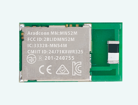
OPTOLEK Bluetooth module solution based on Nordic chip
Anti interference, strong penetration, long-distance transmission, helping to upgrade the intelligence of medical equipment
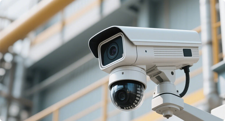
From security cameras, smart homes, to smart cockpits
AI automatic tracking, motion camera
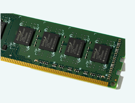
Multi protocol compatible wireless RF and high-throughput storage
For intelligent consumption, wearability, edge computing and AIoT devices


2025-12-25


This validation extends the prior test setup, specifically targeting the connection capability and maximum effective range after the module penetrates a large metal shipping container along each axial direction. This scenario simulates severe conditions common in Industrial Internet of Things (IIoT) applications where signals must penetrate metal structures (e.g., equipment cabinets, walls, or buildings) to ensure the connection stability of IIoT devices within containers and cabinets.
1. Test Objectives
✅ To completely verify the Maximum Effective Communication Range of the MN54L and MN52H series BLE modules when communicating with external devices from inside a large metal container along all axial directions.
✅ To test the communication performance of both the built-in CHIP and PCB antenna version modules when penetrating the container across all axial directions.
2. Test Date & Environment
Item | Details |
Test Date | December 10, 2025 |
Test Environment | Outdoor environment utilizing a standard 40-foot shipping container. The container was parked in an open space. |
3. Equipment Required
Category | Device | Details |
SLAVE/PERIPHERAL | Emitting Board (DUT) | MN54L-C15, MN54L-P15 Modules MN52H-C15, MN52H-P15 Modules |
MASTER/CENTRAL 1 | MN52H-U40 | Tx Power: +8 dBm |
MASTER/CENTRAL 2 | iPhone 7 | Tx Power: 0 dBm |
Test Software | LightBlue®; Aradconn custom BLE firmware. | |
Measurement Tools | Google Maps, Mobile GPS Positioning. |
4. Test Parameters
Parameter | Description |
TX Power | +8 dBm (Set on MN54L, MN52H, and MN52H-U40) |
PHY Mode | 1M (Standard BLE) |
Packet Size | 20 bytes |
Direction | Line-of-sight (LOS) path was maintained for distance, but the signal path was Non-Line-of-Sight (NLOS) due to the container barrier. |
Antenna Position | Inside the furthest end of the 40-foot container. |
Transmission Mode | Connected mode (Verifying valid packet transmission without packet loss). |
Environmental | Temperature: 25°C, Humidity: 66% |
5. Test Procedure - MN52H-U40 (Master, +8 dBm)
5.1 Preparation and Connection Establishment
1. Equipment Setup: Confirmed that the TX Power of both the SLAVE/PERIPHERAL (MN54L-C15/P15, MN52H-C40/P40) and the MASTER/CENTRAL (MN52H-U40) were set to +8 dBm.
2. Transmission Rate: Set to 1M mode with 4 packets transmitted per second.
3. Starting Point: The SLAVE device was placed inside the furthest end of the 40-foot container, the container door was closed, and the antenna was oriented towards the MASTER's driver position.
4. Connection Check: The MASTER established an active connection and performed bidirectional packet transmission. Packet reception was verified via LED indicator lights on the module.
5. Additional Test: The single-axis 125KB mode was also tested to compare the performance difference.
5.2 Distance Measurement and Data Logging
1. Incremental Test: The MASTER moved outwards along the LOS path in 10-meter increments (approx. 10 steps).
2. Monitoring: At each point, the connection status was monitored. Packet loss was identified by the LED indicators extinguishing or blinking irregularly. Continuous transmission/reception defined a valid connection.
3. Angle Test: At the distance where signal attenuation began, the impact of the SLAVE device's antenna rotation on the Packet Success Rate (PSR) was tested to confirm the signal pattern.
4. Maximum Range: Movement continued until significant packet loss occurred (e.g., LED blinking slowed down or stopped). Google Map and GPS were used to precisely record disconnected distance and surrounding environment.
6. Test Procedure - iPhone 7 (Master, 0 dBm)
6.1 Preparation and Connection Establishment
1. Equipment Setup: Established an active connection between the iPhone 7 and the SLAVE devices (MN54L-C15/P15, MN52H-C40/P40), verifying packet reception. Transmission Rate: Set to 1M mode with 4 packets transmitted per second.
2. Transmission Rate: Set to 1M mode with 4 packets transmitted per second.
3. Starting Point Positioning: The SLAVE device was placed inside the furthest end of the 40-foot container, and the door was closed.
4. Connection Check: Connection status was monitored via the LightBlue® application screen.
6.2 Distance Measurement and Data Logging
1. Incremental Test: The MASTER (iPhone 7) moved outwards along the LOS path in 10-meter increments.
2. Monitoring: At each point, connection quality was checked via the LightBlue® screen.
3. Maximum Range: Followed the same procedure as Section 5.2 (Step 4) to determine and log the maximum effective connection distance.
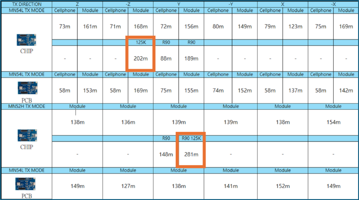
7. Test Results (Maximum Effective Connection Distance)
The table below shows the maximum effective distance at which the MN54L and MN52H series modules maintained a stable bidirectional connection without packet loss after penetrating the container barrier:
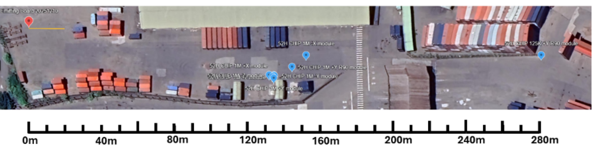
MN54L-C15 Maximum Range Positioning Map (All Axes)

Note: The aerial view is not a photo of the actual site.
MN54L-P15 Maximum Range Positioning Map (All Axes)

Note: The aerial view is not a photo of the actual site.
MN52H-C40 Maximum Range Positioning Map (All Axes)
Note: The aerial view is not a photo of the actual site.
MN2H-P40 Maximum Range Positioning Map (All Axes)

NOTE: THE AERIAL VIEW IS NOT A PHOTO OF THE ACTUAL SITE.
★ Source: Arad Connectivity Co., Ltd. / The content of this article has obtained the authorization for promotion, release and reprint from Arad Connectivity Co.,Ltd.
For more information on Bluetooth wireless modules and other product solutions, please visit our website or contact us by email.
You can leave your contact information, and we will get in touch with you as soon as possible

Scan WeChat
Copyright © Dongguan Optolek Technology Co., Ltd. All Rights Reserved. WEB
Call Us
Scan WeChat